


[fusion_builder_container hundred_percent=”yes” overflow=”visible”][fusion_builder_row][fusion_builder_column type=”1_1″ background_position=”left top” background_color=”” border_size=”” border_color=”” border_style=”solid” spacing=”yes” background_image=”” background_repeat=”no-repeat” padding=”” margin_top=”0px” margin_bottom=”0px” class=”” id=”” animation_type=”” animation_speed=”0.3″ animation_direction=”left” hide_on_mobile=”no” center_content=”no” min_height=”none”][fusion_text] [/fusion_text][fusion_text]
Recomendaciones para una correcta colocación
[/fusion_text][/fusion_builder_column][fusion_builder_column type=”1_1″ last=”yes” spacing=”yes” center_content=”no” hide_on_mobile=”no” background_color=”” background_image=”” background_repeat=”no-repeat” background_position=”left top” hover_type=”none” link=”” border_position=”all” border_size=”0px” border_color=”” border_style=”” padding=”” margin_top=”” margin_bottom=”” animation_type=”” animation_direction=”” animation_speed=”0.1″ animation_offset=”” class=”” id=””][fusion_text]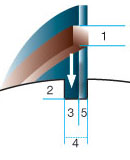 – La altura del cobre (1) deberá ser igual o apenas mayor a la profundidad de la ranura (2) y el espesor (3) debera ser igual al ancho de ranura (4), menos el espesor de la cuchilla a colocar (5).[/fusion_text][/fusion_builder_column][fusion_builder_column type=”1_1″ background_position=”left top” background_color=”” border_size=”” border_color=”” border_style=”solid” spacing=”yes” background_image=”” background_repeat=”no-repeat” padding=”” margin_top=”0px” margin_bottom=”0px” class=”” id=”” animation_type=”” animation_speed=”0.3″ animation_direction=”left” hide_on_mobile=”no” center_content=”no” min_height=”none”][fusion_separator style_type=”single solid” top_margin=”24px” bottom_margin=”44px” sep_color=”#adadad” border_size=”1px” icon=”” icon_circle=”” icon_circle_color=”” width=”90%” alignment=”center” class=”” id=””/][/fusion_builder_column][fusion_builder_column type=”1_1″ last=”yes” spacing=”yes” center_content=”no” hide_on_mobile=”no” background_color=”” background_image=”” background_repeat=”no-repeat” background_position=”left top” hover_type=”none” link=”” border_position=”all” border_size=”0px” border_color=”” border_style=”” padding=”” margin_top=”” margin_bottom=”” animation_type=”” animation_direction=”” animation_speed=”0.1″ animation_offset=”” class=”” id=””][fusion_text]
CARACTERISTICAS DE LA CUCHILLA MONOMETÁLICAS Y SUS VENTAJAS
– Nuestras cuchillas de carácter monometálicas son sometidas a procesos de carbonitruración que logran una uniformidad de dureza en toda la cara cortante de la cuchilla. Esta particularidad de poseer una única cara cortante beneficia, tanto al re-cuchillado del cilindro, en tanto que evita problemas de quiebre y roturas; y al mismo tiempo, protege al operario de la empresa ante cualquier eventualidad producida por el cuero, ya que esta característica de la cuchilla provoca que se voltee y no se destruya.[/fusion_text][/fusion_builder_column][fusion_builder_column type=”1_1″ background_position=”left top” background_color=”” border_size=”” border_color=”” border_style=”solid” spacing=”yes” background_image=”” background_repeat=”no-repeat” padding=”” margin_top=”0px” margin_bottom=”0px” class=”” id=”” animation_type=”” animation_speed=”0.3″ animation_direction=”left” hide_on_mobile=”no” center_content=”no” min_height=”none”][fusion_separator style_type=”single solid” top_margin=”24px” bottom_margin=”44px” sep_color=”#adadad” border_size=”1px” icon=”” icon_circle=”” icon_circle_color=”” width=”90%” alignment=”center” class=”” id=””/][/fusion_builder_column][fusion_builder_column type=”1_1″ last=”yes” spacing=”yes” center_content=”no” hide_on_mobile=”no” background_color=”” background_image=”” background_repeat=”no-repeat” background_position=”left top” hover_type=”none” link=”” border_position=”all” border_size=”0px” border_color=”” border_style=”” padding=”” margin_top=”” margin_bottom=”” animation_type=”” animation_direction=”” animation_speed=”0.1″ animation_offset=”” class=”” id=””][fusion_text]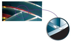 – el corte oblicuo en el extremo de las cuchillas, con el ángulo apropiado para cada modelo, asegura el apoyo perfecto sobre la cuchilla opuesta, lográndose así un óptimo rebajado sin rayar ni marcar el cuero tratado, agilizándose además los tiempos de re-cuchillado.[/fusion_text][/fusion_builder_column][fusion_builder_column type=”1_1″ background_position=”left top” background_color=”” border_size=”” border_color=”” border_style=”solid” spacing=”yes” background_image=”” background_repeat=”no-repeat” padding=”” margin_top=”0px” margin_bottom=”0px” class=”” id=”” animation_type=”” animation_speed=”0.3″ animation_direction=”left” hide_on_mobile=”no” center_content=”no” min_height=”none”][fusion_separator style_type=”single solid” top_margin=”24px” bottom_margin=”44px” sep_color=”#adadad” border_size=”1px” icon=”” icon_circle=”” icon_circle_color=”” width=”90%” alignment=”center” class=”” id=””/][/fusion_builder_column][fusion_builder_column type=”1_1″ last=”yes” spacing=”yes” center_content=”no” hide_on_mobile=”no” background_color=”” background_image=”” background_repeat=”no-repeat” background_position=”left top” hover_type=”none” link=”” border_position=”all” border_size=”0px” border_color=”” border_style=”” padding=”” margin_top=”” margin_bottom=”” animation_type=”” animation_direction=”” animation_speed=”0.1″ animation_offset=”” class=”” id=””][fusion_text]
 – Todas las cuchillas, tanto derechas como izquierdas, deben colocarse con las puntas pintadas hacia el centro del cilindro de cuchillas.[/fusion_text][/fusion_builder_column][fusion_builder_column type=”1_1″ background_position=”left top” background_color=”” border_size=”” border_color=”” border_style=”solid” spacing=”yes” background_image=”” background_repeat=”no-repeat” padding=”” margin_top=”0px” margin_bottom=”0px” class=”” id=”” animation_type=”” animation_speed=”0.3″ animation_direction=”left” hide_on_mobile=”no” center_content=”no” min_height=”none”][fusion_separator style_type=”single solid” top_margin=”24px” bottom_margin=”44px” sep_color=”#adadad” border_size=”1px” icon=”” icon_circle=”” icon_circle_color=”” width=”90%” alignment=”center” class=”” id=””/][/fusion_builder_column][fusion_builder_column type=”1_1″ last=”yes” spacing=”yes” center_content=”no” hide_on_mobile=”no” background_color=”” background_image=”” background_repeat=”no-repeat” background_position=”left top” hover_type=”none” link=”” border_position=”all” border_size=”0px” border_color=”” border_style=”” padding=”” margin_top=”” margin_bottom=”” animation_type=”” animation_direction=”” animation_speed=”0.1″ animation_offset=”” class=”” id=””][fusion_text]
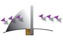 – El cobre utilizado en la colocación deberá ubicarse del lado anterior al giro del cilindro. De esta forma, quedará la cuchilla recostada sobre la pared del cilindro y no sobre el material de calce, evitando vibraciones y problemas de marcas, logrando su óptimo funcionamiento, en corte y rendimientos.[/fusion_text][/fusion_builder_column][fusion_builder_column type=”1_1″ background_position=”left top” background_color=”” border_size=”” border_color=”” border_style=”solid” spacing=”yes” background_image=”” background_repeat=”no-repeat” padding=”” margin_top=”0px” margin_bottom=”0px” class=”” id=”” animation_type=”” animation_speed=”0.3″ animation_direction=”left” hide_on_mobile=”no” center_content=”no” min_height=”none”][fusion_separator style_type=”single solid” top_margin=”24px” bottom_margin=”44px” sep_color=”#adadad” border_size=”1px” icon=”” icon_circle=”” icon_circle_color=”” width=”90%” alignment=”center” class=”” id=””/][fusion_text]
Medidas necesarias para la correcta identificación de la cuchilla:
[/fusion_text][/fusion_builder_column][fusion_builder_column type=”1_1″ last=”yes” spacing=”yes” center_content=”no” hide_on_mobile=”no” background_color=”” background_image=”” background_repeat=”no-repeat” background_position=”left top” hover_type=”none” link=”” border_position=”all” border_size=”0px” border_color=”” border_style=”” padding=”” margin_top=”” margin_bottom=”” animation_type=”” animation_direction=”” animation_speed=”0.1″ animation_offset=”” class=”” id=””][fusion_text]Diámetro Fondo de Ranura:
 – se deberá tomar la medida externa del cilindro por medio de un calibre, o bien a través del cálculo del mismo a partir de la medida de su perímetro.
– Se determinará el diámetro fondo de ranura, restando a esta medida dos veces la profundidad de la ranura[/fusion_text][/fusion_builder_column][fusion_builder_column type=”1_2″ last=”no” spacing=”yes” center_content=”no” hide_on_mobile=”no” background_color=”” background_image=”” background_repeat=”no-repeat” background_position=”left top” hover_type=”none” link=”” border_position=”all” border_size=”0px” border_color=”” border_style=”” padding=”” margin_top=”” margin_bottom=”” animation_type=”” animation_direction=”” animation_speed=”0.1″ animation_offset=”” class=”” id=””][fusion_imageframe lightbox=”no” lightbox_image=”” style_type=”none” hover_type=”none” bordercolor=”” bordersize=”0px” borderradius=”0″ stylecolor=”” align=”none” link=”” linktarget=”_self” animation_type=”0″ animation_direction=”down” animation_speed=”0.1″ animation_offset=”” hide_on_mobile=”no” class=”” id=””]  [/fusion_imageframe][fusion_text]Figura 1: Medida externa del cilindro[/fusion_text][/fusion_builder_column][fusion_builder_column type=”1_2″ last=”yes” spacing=”yes” center_content=”no” hide_on_mobile=”no” background_color=”” background_image=”” background_repeat=”no-repeat” background_position=”left top” hover_type=”none” link=”” border_position=”all” border_size=”0px” border_color=”” border_style=”” padding=”” margin_top=”” margin_bottom=”” animation_type=”” animation_direction=”” animation_speed=”0.1″ animation_offset=”” class=”” id=””][fusion_imageframe lightbox=”no” lightbox_image=”” style_type=”none” hover_type=”none” bordercolor=”” bordersize=”0px” borderradius=”0″ stylecolor=”” align=”none” link=”” linktarget=”_self” animation_type=”0″ animation_direction=”down” animation_speed=”0.1″ animation_offset=”” hide_on_mobile=”no” class=”” id=””]
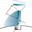
  [/fusion_imageframe][fusion_text]Figura 2: Diámetro fondo de ranura[/fusion_text][/fusion_builder_column][fusion_builder_column type=”1_1″ background_position=”left top” background_color=”” border_size=”” border_color=”” border_style=”solid” spacing=”yes” background_image=”” background_repeat=”no-repeat” padding=”” margin_top=”0px” margin_bottom=”0px” class=”” id=”” animation_type=”” animation_speed=”0.3″ animation_direction=”left” hide_on_mobile=”no” center_content=”no” min_height=”none”][fusion_separator style_type=”single solid” top_margin=”24px” bottom_margin=”44px” sep_color=”#adadad” border_size=”1px” icon=”” icon_circle=”” icon_circle_color=”” width=”90%” alignment=”center” class=”” id=””/][/fusion_builder_column][fusion_builder_column type=”1_1″ last=”yes” spacing=”yes” center_content=”no” hide_on_mobile=”no” background_color=”” background_image=”” background_repeat=”no-repeat” background_position=”left top” hover_type=”none” link=”” border_position=”all” border_size=”0px” border_color=”” border_style=”” padding=”” margin_top=”” margin_bottom=”” animation_type=”” animation_direction=”” animation_speed=”0.1″ animation_offset=”” class=”” id=””][fusion_text]Paso:
 – Se deberá identificar perfectamente una ranura / cuchilla.
– Se determinará el paso midiendo en forma longitudinal al cilindro la distancia desde un extremo hasta que la ranura / cuchilla de una vuelta completa alrededor del cilindro, es decir, hasta que la misma vuelva a cortar la línea de medición.[/fusion_text][/fusion_builder_column][fusion_builder_column type=”1_2″ last=”no” spacing=”yes” center_content=”no” hide_on_mobile=”no” background_color=”” background_image=”” background_repeat=”no-repeat” background_position=”left top” hover_type=”none” link=”” border_position=”all” border_size=”0px” border_color=”” border_style=”” padding=”” margin_top=”” margin_bottom=”” animation_type=”” animation_direction=”” animation_speed=”0.1″ animation_offset=”” class=”” id=””][fusion_imageframe lightbox=”no” lightbox_image=”” style_type=”none” hover_type=”none” bordercolor=”” bordersize=”0px” borderradius=”0″ stylecolor=”” align=”none” link=”” linktarget=”_self” animation_type=”0″ animation_direction=”down” animation_speed=”0.1″ animation_offset=”” hide_on_mobile=”no” class=”” id=””]  [/fusion_imageframe][fusion_text]Figura 3: Paso sin cuchillas [/fusion_text][/fusion_builder_column][fusion_builder_column type=”1_2″ last=”yes” spacing=”yes” center_content=”no” hide_on_mobile=”no” background_color=”” background_image=”” background_repeat=”no-repeat” background_position=”left top” hover_type=”none” link=”” border_position=”all” border_size=”0px” border_color=”” border_style=”” padding=”” margin_top=”” margin_bottom=”” animation_type=”” animation_direction=”” animation_speed=”0.1″ animation_offset=”” class=”” id=””][fusion_imageframe lightbox=”no” lightbox_image=”” style_type=”none” hover_type=”none” bordercolor=”” bordersize=”0px” borderradius=”0″ stylecolor=”” align=”none” link=”” linktarget=”_self” animation_type=”0″ animation_direction=”down” animation_speed=”0.1″ animation_offset=”” hide_on_mobile=”no” class=”” id=””]
  [/fusion_imageframe][fusion_text]Figura 3: Paso con cuchilla [/fusion_text][/fusion_builder_column][fusion_builder_column type=”1_1″ background_position=”left top” background_color=”” border_size=”” border_color=”” border_style=”solid” spacing=”yes” background_image=”” background_repeat=”no-repeat” padding=”” margin_top=”0px” margin_bottom=”0px” class=”” id=”” animation_type=”” animation_speed=”0.3″ animation_direction=”left” hide_on_mobile=”no” center_content=”no” min_height=”none”][fusion_separator style_type=”single solid” top_margin=”24px” bottom_margin=”44px” sep_color=”#adadad” border_size=”1px” icon=”” icon_circle=”” icon_circle_color=”” width=”90%” alignment=”center” class=”” id=””/][/fusion_builder_column][fusion_builder_column type=”1_1″ last=”yes” spacing=”yes” center_content=”no” hide_on_mobile=”no” background_color=”” background_image=”” background_repeat=”no-repeat” background_position=”left top” hover_type=”none” link=”” border_position=”all” border_size=”0px” border_color=”” border_style=”” padding=”” margin_top=”” margin_bottom=”” animation_type=”” animation_direction=”” animation_speed=”0.1″ animation_offset=”” class=”” id=””][fusion_text]Ancho de Trabajo:
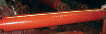
Figura 4: Ancho de trabajo
– Se obtendrá a través de la medición longitudinal del cilindro entre los extremos de la zona de trabajo (zona de ranuras).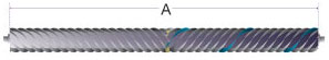 [/fusion_text][/fusion_builder_column][/fusion_builder_row][/fusion_builder_container]